English
 русский
 Español
 عربى
عربىHow Does Lost Foam Casting Work?
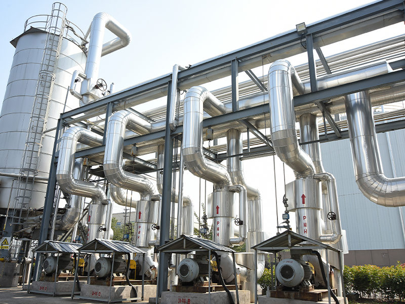
Lost Foam Casting (LFC), also known as evaporative pattern casting or full mold casting, is a revolutionary near-net-shape precision casting technology. Its core principle involves creating a foam plastic model identical to the final casting, coating it with a special refractory coating, embedding it in dry sand, compacting the sand via vibration, and then pouring molten metal directly onto the model. The foam model rapidly vaporizes, decomposes, and disappears, allowing the molten metal to occupy the mold cavity. After cooling and solidification, a casting that precisely replicates the shape of the foam model is formed. This technology integrates materials science, thermodynamics, fluid mechanics, and precision manufacturing processes, holding a crucial position in modern foundry due to its unique advantages.
I. Core Principles and Essence of Lost Foam Casting: Pyrolytic Replacement and Physical Conservation
The secret of lost foam casting lies in the fundamental principle of "pyrolytic replacement". The entire process strictly adheres to the laws of physical conservation (mass, momentum, and energy conservation) and achieves precise metal replacement of the foam model through a series of complex physical and chemical changes:
Pyrolysis and Disappearance of the Foam Model:
- Physical Stage (Melting and Softening): When the molten metal front contacts the foam model (typically made of expanded polystyrene, EPS, or a copolymer like STMMA), intense heat transfer occurs. The glass transition temperature (~100°C) and melting point (~170–240°C) of the foam are far lower than the molten metal temperature (e.g., steel >1500°C). The model surface undergoes drastic softening and melting, forming a liquid front layer.
- Chemical Stage (Pyrolysis, Cracking, and Gasification): Under high temperatures and low-oxygen conditions (due to the shielding effect of the coating and dry sand), the molten polymer chains break, undergoing complex pyrolysis reactions. This endothermic process generates small-molecule gases (mainly styrene monomer, benzene, toluene, ethylbenzene, hydrogen, CO, CO₂, methane, and other hydrocarbons) and minor amounts of liquid tar residues (e.g., liquid polystyrene). Gases escape through the coating and sand pores, while liquid products are partially decomposed by the high temperature; some may be pushed by the metal front to the coating interface or remain on the casting surface (causing defects if not controlled).
Gas Gap Formation and Interface Reaction: A narrow gas-filled gap forms between the molten metal front and the undecomposed foam model. This unique feature of LFC dictates metal filling behavior, front stability, heat transfer, and casting quality (e.g., carbon fold defects).
Metal Filling and Solidification:
- Vacuum-Assisted Gravity Pouring: Metal is poured into the pouring cup under gravity, while the entire flask is subjected to vacuum (0.3–0.7 bar). Vacuum significantly enhances mold filling by:
- Suction Effect: Continuously extracting gases/liquids from the decomposing foam through the permeable coating and dry sand system, accelerating their removal from the cavity and preventing gas back-pressure from hindering metal flow.
- Mold Strength Enhancement: Creates a pressure difference between loose dry sand particles, compacting them tightly and giving the mold high strength and rigidity. This avoids issues associated with binders in traditional sand casting, enabling the casting of complex thin-walled parts.
- Improved Metallurgical Quality: Helps reduce gas entrapment in the metal and may promote inclusion flotation (aided by the gating/riser system).
- Front Advancement Mode: The metal does not advance steadily as a whole but gradually replaces the foam model in a quasi-laminar ("layer-like") manner, preceded by a narrow gap filled with pyrolytic gases. The stability of this front is crucial for replicating fine model details.
- Solidification and Shaping: After the metal completely fills the cavity, heat dissipates through the coating and dry sand, initiating solidification. Due to the relatively low thermal conductivity of dry sand, solidification is typically slower (depending on casting wall thickness and alloy type), aiding feeding and reducing stress. Solidification ultimately forms a metal casting highly consistent with the geometry of the original foam model.
Essence Summary: Lost foam casting is a dynamic replacement process where intense physical (melting, vaporization, escape) and chemical (polymer pyrolysis/cracking) changes are tightly integrated. Molten metal utilizes its high thermal energy, aided by the driving force provided by vacuum and guaranteed gas removal channels, to precisely replace the easily vaporized foam plastic model in-situ with itself solidifying into a solid metal entity, achieving "replace foam with heat, substitute plastic with metal".
II. Detailed Process Flow of Lost Foam Casting
Lost foam casting is a multi-step systems engineering process where each step requires precise control to ensure final casting quality:
-
Foam Pattern Making: The starting point and foundation for precision.
- Raw Material Selection:
- Expandable Polystyrene (EPS): Most common, low cost, excellent foaming moldability, good dimensional stability, mature pre-expansion and aging process. Drawbacks: Incomplete pyrolysis, high carbon residue (2-4%), viscous liquid products (mainly liquid polystyrene), prone to carbon folds, carbon pickup (especially in low-carbon steel), and lustrous carbon defects. Gas products have high molecular weight (e.g., styrene monomer), increasing exhaust burden. Applicable: Preferred for cast iron (gray iron, ductile iron - less sensitive to carburization) and non-ferrous alloys (Al, Cu). For small/medium steel castings with non-critical surface requirements, strict process control is needed.
- Expandable Methyl Methacrylate-Styrene Copolymer (STMMA): Copolymer of styrene (St) and methyl methacrylate (MMA). The MMA component increases oxygen content, leading to more complete and faster pyrolysis. Carbon residue is significantly lower than EPS (<0.5%, even 0.02%), liquid products are minimal and have low molecular weight/easily vaporize, gas products have low molecular weight (CO₂, CO, H₂) and are easily expelled. Significantly reduces carbon folds and carburization, improving surface quality. Drawbacks: Higher cost (30-50% more than EPS), slightly higher molding shrinkage (requires mold compensation), slightly lower rigidity (large parts need reinforcement), some formulations may soften/deform at high temperatures. Applicable: Preferred material for steel castings (especially low-carbon and stainless steel). High-quality, complex thin-walled cast iron and non-ferrous castings. Key material for improving LFC casting quality (especially surface and material purity). MMA content should be optimized based on alloy type (steel/iron), wall thickness, and pouring temperature (commonly 15-30%).
- Expandable Polypropylene (EPP): Advantages: Extremely low pyrolysis residue (almost completely vaporized), virtually no carbon black or lustrous carbon issues. Drawbacks: Difficult foaming (high temperature required), poor surface finish, low strength prone to deformation, difficult dimensional control, high cost. Applicable: Very limited, mainly for special requirements (e.g., extremely low carburization).
- Raw Material Form: Pre-expandable beads containing a blowing agent (e.g., pentane).
- Pre-Expansion (Pre-Expansion): Beads are softened in a pre-expander (steam heated), the blowing agent vaporizes and expands, increasing bead volume to a set density (typically 2-5 times the final pattern density). Temperature, time, and steam pressure are strictly controlled to obtain uniform pre-expanded beads with a closed-cell structure and target density (directly affecting pattern strength, surface quality, and pyrolysis product quantity).
- Aging/Stabilization: Pre-expanded beads develop negative pressure internally. They must be stored in air for a period (8-48 hours) to allow air infiltration internally, balance pressure, dry, stabilize, and gain elasticity, preventing excessive shrinkage or deformation during molding.
- Molding (Molding): Aged beads are fed into a molding die.
- Mold: Typically aluminum alloy with dense vent holes (diameter ~0.3-0.8mm).
- Process: Beads fill mold cavity -> Steam introduced for heating (secondary expansion, softening, bonding) -> Cooling water cools and sets -> Vacuum-assisted demolding. Molding temperature, pressure, time, and steam quality are critical for pattern density, fusion, and surface finish. High-quality patterns should be uniformly dense, well-fused, smooth-surfaced, dimensionally accurate, and warp-free.
- Raw Material Selection:
-
Pattern Cluster Assembly (Cluster Assembly): Individual foam patterns (may include multiple part patterns), gating system (sprue, runners, ingates), and riser system (feed risers, slag traps), typically machined from EPS/STMMA rods. They are precisely bonded using specialized eco-friendly hot-melt adhesives (to avoid excessive gas/residue) forming a complete pattern cluster (Cast Cluster). Assembly quality directly impacts metal flow and casting integrity.
-
Pattern Drying and Repair: The assembled cluster must be thoroughly dried (removing moisture). Defects on the pattern surface (e.g., fusion line depressions, small holes, minor damage) are repaired and polished to ensure surface quality.
-
Pattern Cluster Coating (Coating): The coating is a critical barrier and functional layer for LFC success.
- Functions:
- Support Model: Provides sufficient rigidity to the fragile foam pattern, preventing deformation/damage during molding vibration.
- Isolation Barrier: Prevents pyrolysis products (liquid tar, carbon black) from penetrating dry sand (contaminating sand) or sticking back to the casting surface (causing defects).
- Permeability Channel: Excellent permeability is essential to allow large volumes of gas generated during foam pyrolysis to escape rapidly through the coating into the dry sand, where it is evacuated by the vacuum system. Permeability is one of the most important coating properties.
- Refractory Protection: Withstands the impact and thermal effects of molten metal, protecting dry sand from sintering.
- Surface Finish: Affects casting surface quality and contour definition.
- Aids Shell Removal: After cooling, the coating should easily separate from the casting.
- Composition:
- Refractory Aggregates: Main component (typically 60-75% by dry weight). Common types: Zircon sand/flour (ZrSiO₄, high refractoriness/thermal conductivity, inert, excellent surface finish, high cost, used on critical surfaces), Silica flour (SiO₂, common, low cost), Bauxite (Al₂O₃, good high-temp performance), Mullite, Kyanite, Graphite powder, etc. Particle size distribution must be reasonable to ensure coating strength and permeability.
- Binders: Provide green and dry strength. Water-based common: Sodium/Calcium bentonite, Silica sol, Alumina sol, CMC, Polyvinyl Alcohol (PVA), Latex (LA), Resins. Alcohol-based: Hydrolyzed ethyl silicate. Type and amount affect strength, permeability, crack resistance.
- Suspension Agents/Carriers: Keep aggregates suspended stably. Water-based: Bentonite, organic polymers (e.g., CMC). Alcohol-based: Organic bentonite, PVB.
- Additives: Improve rheology (deflocculants), anti-corrosion (biocides), defoamers, surfactants (improve wettability), anti-cracking agents, etc.
- Coating Preparation: Strictly control component ratios, addition sequence, mixing time and intensity (high-speed disperser), viscosity (measured by flow cup or rotational viscometer). Coating requires sufficient hydration (typically aged >24 hours) to achieve stable optimal performance.
- Coating Application Process:
- Dipping: Entire cluster immersed in coating tank, slowly withdrawn. Requires uniform thickness, no runs/sags, no pooling, no bubbles.
- Pouring/Brushing: Suitable for large parts or local repairs.
- Coating Thickness: Typically 0.5-2.0mm, depending on casting size, wall thickness, alloy type (steel requires thicker coatings). Critical areas (e.g., near ingates, hot spots) can be locally thickened.
- Drying: Coating must be thoroughly dried and cured (moisture content <1%). Common methods:
- Ambient Drying: Long time (24-48 hours), prone to deformation.
- Low-Temperature Drying (≤50°C): Accelerates drying, humidity and airflow control are key.
- Dehumidification Drying: Most effective, efficient (can reduce to hours), precise control of temperature/humidity (e.g., 30-40°C, humidity<30%), minimal pattern deformation. Modern mainstream method.
- Coating Inspection: Check thickness (gauge), surface quality (visual), permeability (special permeability tester), strength (scratch or sand abrasion test).
- Functions:
-
Molding (Vibration Compaction):
- Flask Preparation: Specialized flask with vacuum chambers and filter screens (metal mesh or permeable bricks) on walls, connected to vacuum system.
- Molding Sand: Use dry (moisture <0.5%), binder-free silica sand (common AFS 40-70, i.e., 0.212–0.425mm) or specialty sands (chromite sand, zircon sand, olivine sand for special requirement areas). Sand temperature generally controlled <50°C. Sand requires regular dedusting and cooling.
- Pattern Cluster Placement: Carefully place the coated, dried cluster into the bottom of the flask, aligning the pouring cup position with the pouring station.
- Sand Filling & Vibration Compaction:
- Shower Filling: Ensures sand fills evenly and gently around and within the cluster cavities, avoiding pattern impact.
- 3D Micro-Vibration: Flask placed on vibrating table. Uses low amplitude (0.5–1.5mm), medium-high frequency (40–60Hz) micro-vibration. Vibration parameters (time, frequency, amplitude), sand characteristics (size, shape, moisture), and filling speed jointly determine compaction effectiveness.
- Compaction Goal: Achieve highly uniform and sufficient compaction density (>80% theoretical density typically required) in the sand surrounding the pattern and within complex cavities, forming a strong shell to support the coated pattern against metalostatic pressure and thermal shock, preventing mold collapse, mold wall movement, sand penetration, and dimensional deviation. Insufficient compaction is the root cause of many defects (e.g., mold wall movement, dimensional errors).
- Process Monitoring: Advanced production lines may use sensors to monitor sand flow, amplitude, frequency, and compaction density (indirectly or directly measured).
- Covering and Sealing: Cover flask top with plastic film (e.g., polyethylene). Seal the film firmly onto the flask flange edge using a sealing strip (often adhesive rubber strip) to ensure vacuum sealing. The film isolates air, preventing air ingress into the cavity during pouring which would disrupt the vacuum field, and prevents sand from being pulled out by vacuum. Place a layer of dry sand or weights on the film to protect it from being burned through by hot metal.
- Connect Vacuum System: Connect flask vacuum ports via hoses to the vacuum pump system. Modern setups often have dedicated vacuum pump sets (liquid ring or rotary vane pumps) per pouring station. Vacuum lines include filters to prevent sand ingress.
-
Pouring:
- Vacuum Activation: Start vacuum pump seconds to tens of seconds before pouring to achieve and stabilize the set vacuum level in the flask (typically 0.3–0.7 bar / 0.03-0.07 MPa absolute pressure). Vacuum level is a core process parameter, optimized based on casting structure (higher for complex thin walls), alloy type (iron, steel, non-ferrous), pour weight/speed.
- Metal Treatment and Temperature Control: Perform necessary metal treatment (refining, modification, inoculation) and precisely control pouring temperature (slightly higher than sand casting to compensate for foam vaporization heat absorption). Typical temps: Gray iron 1350-1450°C, Ductile iron 1380-1480°C, Steel 1550-1650°C, Aluminum alloy 680-760°C.
- Pouring Operation:
- High flow rate, fast, steady, continuous: Keep pouring cup full, ensure sprue fills quickly to create siphon effect. Avoid interruptions or splashing.
- Pouring Time: Optimized based on casting weight, wall thickness, structure. Too long increases pyrolysis products; too short may cause turbulence, air entrapment, misrun. Usually synchronized with vacuum hold time.
- Monitoring: Large or critical castings may use automatic pouring machines. Operators must closely monitor pouring cup level.
-
Cooling and Vacuum Release: After pouring, vacuum must be maintained for a period (minutes to tens of minutes) until the casting surface has completely solidified into a strong enough shell to resist sand pressure. Releasing vacuum too early can cause casting distortion, mold wall movement, or even collapse. The casting continues cooling in the mold to a safe temperature (typically <500°C, depending on alloy and size), utilizing the slow cooling characteristic of dry sand to reduce stress.
-
Shakeout and Cleaning:
- Sand Removal: Remove top protective sand and film. Transfer flask to vibrating shakeout machine (or use turnover fixture).
- Shakeout: Vibrate dry sand away from the casting. Dry sand has excellent flowability, making shakeout easy, clean, with far less noise and dust than traditional sand molds. The shakeout casting cluster (casting + gating/riser system + coating shell) is conveyed out.
- Sand Processing: Shaken-out sand is screened (remove debris, large coating fragments), cooled (fluidized bed cooler, boiling cooler, etc.), dedusted (baghouse system), and returned to sand hoppers for reuse. Sand temperature, grain size distribution, and dust content require periodic testing.
- Remove Gating/Risers: After the casting cools to room temperature, remove the gating and riser systems via cutting (grinding wheel, gas cutting), knocking (hammering, impact), or specialized equipment.
- Coating Removal: Use vibrating shakeout equipment or shot blasting to remove most adhering refractory coating. Residual coating in deep holes/internal cavities may require sandblasting, high-pressure water jetting, or chemical cleaning.
- Finishing: Grind off gating/riser remnants, fins, burrs. Perform sandblasting, polishing, etc., for castings with high surface finish requirements.
III. Key Technical Advantages and Characteristics of Lost Foam Casting
The success of lost foam casting stems from its unique and significant advantages:
-
Extreme Design Freedom and Near-Net Shape:
- Foam patterns are easily machined and bonded, enabling the production of highly complex hollow structures, internal passages, curved channels (e.g., engine blocks/heads, impellers, complex valve bodies, art pieces), breaking limitations of traditional parting lines and pattern removal.
- Reduces or eliminates machining (e.g., complex oil/water passages), achieving near-net-shape manufacturing, saving material and machining costs.
- Can produce as a single piece components that traditionally require multiple castings and assembly (e.g., pump housing with flange, bent pipe), reducing subsequent welding/assembly steps and potential leak paths.
-
Exceptional Dimensional Accuracy and Surface Quality:
- No parting lines, no need for pattern removal, completely eliminates dimensional errors common in sand casting (flash, mismatch, draft angles, mold wall movement). Dimensional accuracy reaches CT7-CT9 (GB/T 6414), CT10 possible for some complex parts.
- Good foam pattern surface finish (Ra 6.3-12.5μm), good coating replication, resulting castings have good surface finish (Ra 12.5-25μm, Ra 6.3μm possible after shot blasting), sharp contours, good reproduction of details (text, patterns). Reduces cleaning time and subsequent finishing costs.
-
Process Simplification and Increased Efficiency:
- Simplified Steps: Eliminates complex steps in traditional sand casting: sand mixing, molding (flask turning, closing), core making, mold/core hardening/drying (including expensive core boxes). Streamlines the process chain.
- Shorter Cycle Time: Patterns can be produced in advance in large quantities; molding is fast (dry sand vibration compaction); shakeout and cleaning are extremely simple and quick. Overall production cycle is shortened.
- Smaller Footprint: Eliminates need for large sand handling systems (no binders), core sand equipment, drying ovens, etc., leading to compact plant layout.
- Flexible Production: Same flask can cast different shapes (just change pattern cluster), no need for specialized molds (flasks are universal), adaptable to multi-variety, low-volume production. Automated lines allow flexible changeovers.
-
Superior Environmental Performance and Improved Working Conditions:
- No Binders: Uses binder-free dry sand, eliminating hazardous emissions (phenolics, furans, SO₂, alkaline dust) associated with traditional green sand, resin sand, or sodium silicate sand.
- Low Shakeout Dust: Excellent dry sand flowability means almost no dust during shakeout (especially with dust collection systems).
- High Reclaimed Sand Rate: Dry sand can be reused almost 100% after simple cooling and dedusting, drastically reducing solid waste (only minor coating residues). Aligns with circular economy.
- Significantly Reduced Labor Intensity: Avoids heavy ramming, lifting flasks, and sand cleaning. Operating environment significantly improved (reduced noise, dust, heat, harmful gases).
-
Reduced Overall Costs:
- Material Cost: Near-net shape reduces machining allowance (typically 1-3mm), saving metal (especially expensive alloys). High utilization of dry sand and foam materials. Long mold life (aluminum molds can produce tens of thousands of parts).
- Machining Cost: Reduces or eliminates machining steps (e.g., complex oil/water passages).
- Labor Cost: High automation reduces need for skilled molders.
- Management Cost: Simplified process chain reduces work-in-process inventory.
- Scrap Rate: With good process control, scrap rate can be kept low (<5%).
- Energy Consumption: Eliminates mold/core hardening/drying; sand doesn't need regeneration (just cooling/dedusting). Overall energy consumption is typically lower than traditional sand casting.
IV. Key Considerations for Material Selection
-
Foam Pattern Material:
- Selection Basis: Primary consideration is casting material (steel/iron/non-ferrous), quality requirements (especially surface, limits on carburization), cost. Secondary factors: casting size, structural complexity (affecting pattern strength needs). STMMA is becoming mainstream for high-end applications (automotive, pumps/valves, key construction machinery parts).
-
Refractory Coating (Coating): As described, the coating is a core functional material. Its composition (aggregates, binders, additives), properties (permeability, strength, refractoriness, coating ability), preparation process (mixing/dispersion, aging), and application (dipping, drying) require strict standardization and control. Coating permeability is the lifeline for smooth gas escape.
-
Molding Sand:
- Silica Sand: Most common, low cost, widely available. Use dry, round or sub-angular, well-graded sand (common AFS 40-70). Dust content must be low (<0.5%), requires regular dedusting and cooling.
- Specialty Sands: Chromite sand, Zircon sand, Olivine sand, etc. Used for special requirement areas (e.g., thick steel section hot spots, areas prone to sand penetration). Utilize advantages like high refractoriness, high thermal conductivity, low thermal expansion, chemical inertness to prevent sand penetration, sintering, and hot tearing. Usually expensive, used locally (facing sand).
-
Metal Alloys:
- Cast Iron (Gray Iron, Ductile Iron): Most widely used and mature LFC application. Relatively forgiving process window (especially with EPS). Widely used in automotive (chassis brackets, exhaust manifolds, engine blocks), agriculture, valves, pipe fittings, machine tool components.
- Cast Steel (Carbon Steel, Low-Alloy Steel, High-Manganese Steel, Stainless Steel): Huge potential but technically demanding. Must use STMMA (or very high MMA content), strict process control (pouring temp, vacuum, coating permeability, gating design) to prevent carburization, porosity, inclusions, carbon folds. Used for pump/valve bodies, wear parts (liners, hammers), construction machinery parts, hardware.
- Aluminum Alloys, Magnesium Alloys, Copper Alloys: Significant advantages (complex thin walls, good surface finish), increasing applications (automotive intake manifolds, cylinder heads, transmission housings, aerospace parts, art castings). Lower pouring temp makes foam decomposition relatively milder, but care needed to prevent entrapment of pyrolysis products causing porosity/inclusions. High permeability coating crucial. High pattern strength required (prevent deformation during molding). Magnesium alloys require special safety measures (fire/explosion prevention).
V. Analysis of Typical Lost Foam Casting Defects, Causes, and Prevention Measures
Despite its advantages, the unique physical chemistry of LFC presents specific defect challenges:
-
Carbon Fold / Resin Rich Layer:
- Phenomenon: Irregular, wrinkled, dark-colored defects on casting surface (especially upper surfaces, below thick-thin transitions). Severe cases may show lustrous carbon film.
- Causes: Liquid pyrolysis products (mainly liquid polystyrene/tar) fail to vaporize/escape promptly and are pushed by the advancing metal front to the coating interface. Turbulence or fluctuations at the solidification front entrap or envelop these viscous liquids onto the metal surface, forming folds. Gas gap pressure fluctuations and unstable metal front advance exacerbate this. EPS is much more prone than STMMA.
- Prevention Measures:
- Pattern Material: Prefer STMMA over EPS. Ensure uniform pattern density and good fusion.
- Coating: Increase permeability is key! Optimize formula (aggregate gradation, binder type/amount), ensure thorough drying (wet coating has poor permeability). Increase permeability/thickness locally in prone areas.
- Vacuum Process: Ensure sufficient vacuum (especially early in pour) and stable pumping capacity. Optimize vacuum profile (e.g., pre-pour high vacuum, stable during pour). Ensure system sealing integrity (film, pipes).
- Gating System: Design for fast, stable filling, avoiding turbulence or stagnant flow. Top gating aids gas venting but impacts pattern; bottom gating is steadier but gas path is longer. Step gating, slot gating common.
- Pouring Process: Control pouring temp (too high increases liquid viscosity, too low reduces fluidity). Ensure fast enough pouring speed (fill sprue quickly for siphon), avoid splashing entraining gas.
- Cluster Design: Avoid large flat surfaces, add process ribs/vents to channel pyrolysis products.
-
Carbon Pickup:
- Phenomenon: Significantly higher carbon content in casting surface/layers (especially thick section cores, near hot spots) compared to furnace chemistry. Particularly sensitive/harmful in steel (especially low-carbon).
- Causes: Solid carbon residues (coke, lustrous carbon) from incomplete pyrolysis dissolve into hot steel (high carbon solubility). Primarily from EPS benzene ring pyrolysis. High pattern density, slow pour speed, high pour temp, low vacuum, poor coating permeability extend residue contact time, worsening carburization. STMMA significantly reduces risk.
- Prevention Measures:
- Pattern Material: Must use STMMA for steel! Reduce pattern density (while maintaining strength). Avoid carbon-rich adhesives.
- Coating: High-melting, inert aggregates (Zircon) can block carbon diffusion. Good permeability accelerates residue removal.
- Vacuum & Pouring: High vacuum accelerates gas removal. Reduce pouring temp (decreases carbon solubility/diffusion). Increase pouring speed (shortens carbon contact time).
- Alloy Design: For sensitive castings, lower target carbon content during melting (allowance for pickup).
- Casting Design: Avoid excessively thick sections (slow solidification, longer carburization time).
-
Gas Porosity:
- Phenomenon: Holes within or near casting surface, walls usually smooth. Classified as entrapped gas porosity (irregular) and invasive gas porosity (round).
- Causes: Extremely complex and diverse:
- Entrapped Pyrolysis Gas: Turbulence from excessive pour speed or poor gating design entraps pyrolysis gases into the metal.
- Gas Invasion Due to Poor Venting: Poor coating/sand permeability, insufficient/unstable vacuum, pour speed exceeding venting capacity, high pattern density causing excessive gas volume prevent timely gas escape. High-pressure gas pockets form at the solidification front and invade solidifying metal.
- Other Sources: Coating moisture vaporizing, gas from metal melt or pouring turbulence, gas evolution during alloy solidification shrinkage.
- Prevention Measures:
- Pattern: Control density, ensure fusion quality. Ensure cluster is dry.
- Coating: Ensure high, uniform permeability! Strict drying control.
- Molding: Ensure sand is uniformly compacted and permeable (control sand temp, grain size).
- Vacuum: Optimize level (avoid too high/low), maintain stability. Ensure pump capacity matches cluster gas generation. Check seals.
- Gating System: Design smooth, low-resistance system (e.g., open) to vent gases with rising metal front (top/step gating better than pure bottom). Increase total ingate area. Use slag traps/risers (often combined with feeders). Keep pouring cup full.
- Pouring Operation: Control pour speed (avoid turbulence, avoid excessive gas gap length). Moderate pouring temp.
- Metal Melting: Perform degassing/refining.
-
Inclusions:
- Phenomenon: Non-metallic foreign bodies within casting. Common in LFC: Coating inclusions (refractory), Foam decomposition inclusions (tar slag, carbon lumps), Sand inclusions.
- Causes:
- Coating Spall/Erosion: Excessive metal impact force damages weak/un-dried/low-strength coating.
- Entrapped Pyrolysis Residues: Liquid/solid residues not fully vaporized/removed are entrapped. Poor pattern fusion creates "sandwich" layers prone to large residue formation.
- Sand Penetration: Local low sand compaction, coating damage/cracking, excessive vacuum sucking sand through coating/flask.
- Prevention Measures:
- Pattern: Ensure strength, secure bonding, smooth defect-free surface. Avoid sharp corners. Repair smoothly.
- Coating: Increase strength (optimize binder) and erosion resistance (high-refractory aggregates). Ensure good adhesion to pattern. Strict drying control (no cracks/delamination).
- Molding: Ensure uniform high sand compaction. Optimize vibration (avoid damaging coating).
- Vacuum: Avoid excessive vacuum damaging coating/sand.
- Gating System: Smooth design, avoid direct metal impingement on pattern/coating weak spots (use runner buffers), install slag traps/filters. Avoid ingates pointing directly at large flats/thin walls.
- Pouring Operation: Avoid metal splashing impact. Position pouring nozzle centrally.
- Metal Melting: Improve slag skimming, filtration (in-mold filters).
-
Dimensional Deviation & Distortion:
- Phenomenon: Casting dimensions out of tolerance, or warped shape.
- Causes:
- Pattern Distortion: Material shrinkage (molding cooling, storage env. changes), improper handling/storage causing deformation, poor bonding, insufficient aging.
- Improper Molding: Sand filling impact or incorrect vibration parameters cause pattern distortion/shifting. Insufficient/uneven sand compaction (mold wall movement during pour).
- Coating Influence: Excessive thickness or drying shrinkage stress causes pattern distortion.
- Restricted Solidification Shrinkage: Excessive sand compaction (especially at hot spots) or poor collapsibility (e.g., using specialty sand) hinder normal contraction, causing hot tears, stress distortion, or oversized dimensions.
- Premature Vacuum Release: Removed before solidified shell has sufficient strength to resist sand pressure, causing distortion (esp. thin-wall large flats).
- Mold Design: Foam molding die did not adequately compensate for pattern shrinkage (EPS ~0.3-0.8%, STMMA slightly higher), coating thickness, and metal shrinkage.
- Prevention Measures:
- Pattern: Strict control of molding process. Ensure aging. Optimize bonding. Stable storage env. Use supports. Precise measurement (3D scanning).
- Mold Design: Precisely calculate and compensate for pattern shrinkage, coating thickness effect, and metal shrinkage (experience + simulation).
- Coating: Control thickness uniformity.
- Molding: Optimize vibration, sand filling. Ensure uniform compaction density (use test equipment). Pre-fill sand/add supports inside complex patterns.
- Process Control: Strictly maintain vacuum until shell is strong enough. Sufficient cooling time for large thin walls.
- Casting Design: Add removable process ribs/tie bars. Optimize structure to reduce stress concentration.
-
Mold Collapse (Cave-In):
- Phenomenon: Partial or large-area collapse of sand mold during/after pouring, causing incomplete or severely deformed casting. Catastrophic defect, typically scrapes entire flask.
- Causes:
- Insufficient Sand Compaction: Most common cause. Incorrect vibration, fine/dusty sand (poor flow), high sand temp, fast/uneven filling.
- Low/Lost Vacuum: Insufficient pump capacity, seal failures (film tear/burn, flange seal damage, flask/filter cracks/blockage, pipe leaks), pump failure, vacuum drop during pour surge.
- Excessive Pour Speed/Impact: High pour speed/metal fall height violently impacts pattern/underlying sand, exceeding local sand strength. Especially weak sprue/bottom areas.
- Poor Cluster Design/Placement: Unstable cluster, large bottom flat overhang shifting during pour, weak bottom support sand.
- Coating Failure: Low strength/un-dried coating erodes under metal/residue pressure, letting metal/gas invade sand layer. Especially near ingates/thin walls.
- Sand Problems: High moisture (>0.5%) generating steam, high dust (>1%) filling voids/reducing friction.
- Premature Vacuum Removal: Before shell is strong enough (esp. thick sections).
- Flask Design: Insufficient/uneven vacuum chamber area on walls, weak flask rigidity.
- Prevention Measures:
- Optimize Vibration Molding: Precise control of parameters. Use 3D vibrators. Monitor compaction density (>80%).
- Improve Sand Filling: Shower/multi-point gentle filling. Control speed.
- Ensure Sand Quality: Dry (<0.5%), clean (<0.5% dust), graded (AFS 40-70), cool (<50°C). Strengthen sand processing.
- Ensure Reliable Vacuum System: Adequate pump capacity/piping. Redundancy/backups.
- Strict Seal Management: Use high-temp resistant film, apply protective sand/blanket. Maintain flange seals. Regular leak inspections/repairs.
- Vacuum Monitoring/Control: Install gauges/sensors, alarms, closed-loop control if possible.
- Maintain Post-Pour Vacuum: Hold until shell is strong enough (minutes to tens of mins).
- Control Pouring Operation: Optimize pour speed (avoid impact). Minimize metal fall height.
- Improve Cluster Design/Placement: Design for sand support, avoid wide overhangs, add supports/feet. Ensure stable placement. Pre-fill difficult cavities cautiously.
- Strengthen Coating: Increase strength/erosion resistance (binders, aggregates). Ensure thorough drying/curing. Ensure uniform thickness, thicken impact zones.
- Flask Maintenance: Regular inspection/repair of structure, seals, filters.
VI. Typical Application Fields and Examples of Lost Foam Casting
Leveraging its unique advantages, LFC finds wide and growing applications in numerous industrial sectors, particularly for complex, high-precision, difficult-to-machine, or weight-reduction components:
-
Automotive Industry: Largest and most mature application.
- Engine Components: Cylinder heads (integral water/oil jackets), intake manifolds (complex flow paths, thin walls, lightweight), engine blocks (partial structures), exhaust manifolds, turbocharger housings (thin-walled, heat-resistant), oil pans, brackets (engine/transmission/chassis—complex geometry, high rigidity).
- Drivetrain: Transmission housings, clutch housings (complex internal cavities, high precision requirements).
- Chassis & Suspension: Steering knuckles, control arms (lightweight, high strength), differential housings.
- Braking System: Brake caliper housings (partial complex structures).
- Others: Water pump housings, oil cooler covers. Key Advantages: Enables lightweight design for fuel efficiency; integrates complex coolant/oil passages to enhance thermal efficiency and reliability; reduces machining and leakage risks; high dimensional accuracy minimizes assembly tolerances; flexible production adapts to model updates.
-
Construction Machinery & Heavy Trucks:
- Hydraulic Components: Valve blocks (complex intersecting holes, deep bores), pump/motor housings (high-pressure sealing, complex flow paths).
- Structural & Wear Parts: Cab brackets, axle housings, gearbox housings, various brackets, wear-resistant liners, hammer heads, jaw plates (high-manganese steel castings with complex contours). Key Advantages: Manufactures complex internal hydraulic components; enables monolithic casting of large structural parts for improved strength; accurately replicates wear surfaces for optimized performance.
-
Pumps, Valves & Fluid Control:
- Pumps: Centrifugal pump housings, impellers (complex curved flow paths, superior hydraulic performance), gear/screw pump housings.
- Valves: Ball/gate/globe/butterfly valve bodies (complex flow paths, high sealing requirements), valve caps, seats.
- Pipe Fittings: Complex pipe joints, multi-outlet fittings. Key Advantages: Smooth internal flow paths minimize turbulence losses; monolithic casting eliminates leakage paths; high precision ensures sealing surface quality and assembly accuracy.
-
Machine Tools & General Machinery:
- Machine tool beds/bases/columns (partial small-medium size; dimensional accuracy, vibration damping).
- Gearbox housings, reducer housings.
- Compressor housings, various brackets, couplings. Key Advantages: Ensures precision of critical mating surfaces; enables monolithic casting of complex housings; high design freedom for damping ribs/structures.
-
Mining & Wear Industry:
- Ball mill liners, crusher liners, jaw plates, hammer heads, bucket teeth (high-chromium iron, high-manganese steel).
- Conveyor system wear parts, bucket components. Key Advantages: Precisely replicates wear profiles; enables complex geometries and internal reinforcements (e.g., embedded carbide inserts); eliminates draft angles to improve material utilization.
-
Pipe Fittings & Hardware:
- Various ductile iron pipe fittings (elbows, tees, crosses, reducers), especially complex/large-diameter types.
- Architectural hardware (brackets, connectors), fire protection fittings. Key Advantages: Forms complex internal cavities without cores; high dimensional accuracy and sealing; high production efficiency and cost-effectiveness.
-
Aerospace (Emerging Field):
- Non-critical load-bearing structures (brackets, housings, frames).
- Engine ancillary components (inlet guide vanes, supports).
- Complex thin-wall aluminum/magnesium alloy parts (leverages weight reduction). Key Advantages: Facilitates complex lightweight structures; reduces part count and joints. Current adoption limited by stringent reliability/certification requirements, but holds significant potential for special alloy precision castings.
-
Art Casting & Special Fields:
- Large sculptures, intricate artworks (metal replication of foam prototypes).
- Musical instrument components (e.g., brass instrument parts).
- Non-implantable medical device housings (complex enclosures). Key Advantages: Perfectly replicates artistic details; enables complex/abstract geometries unachievable by traditional methods.
VII. Technical Limitations and Challenges of Lost Foam Casting
Despite its advantages, LFC has inherent limitations and ongoing challenges:
-
High Tooling Cost & Development Time:
- Initial Investment: Aluminum foam pattern molds are expensive (especially for complex parts). While per-unit cost may be low in mass production, mold cost dominates for prototypes/large single-piece castings.
- Extended Development Cycle: The chain (product design → mold design/manufacture → foam pattern trial/modification → process validation) is longer than traditional wood pattern sand casting trials. 3D-printed prototype patterns accelerate development but mass production still requires metal molds.
-
Size Limitations:
- Foam Pattern Strength: Large thin-wall or slender foam patterns are prone to deformation/breakage during manufacture, handling, coating, and molding. Structural reinforcements (ribs), high-strength foam (high-density STMMA), and internal sand supports alleviate this but impose practical limits (current mass production typically <5m length, <5 tons weight; larger parts require specialized processes/controls).
- Equipment Constraints: Very large castings require enormous flasks, vibrators, cranes, furnaces, and vacuum systems, demanding massive investment.
-
Material & Metallurgical Constraints:
- Carbon-Sensitive Alloys: Eliminating surface carburization remains challenging for low-carbon steels (C<0.2%) and certain stainless steels, even with STMMA, limiting use in ultra-low-carbon applications.
- Very High-Melting-Point Alloys: Matching foam pyrolysis rate to metal front advance, coating refractoriness, and reactions between melt/pyrolysis products are complex for superalloys/titanium alloys; adoption is limited.
- Surface Finish Limit: Superior to conventional sand casting (Ra 6.3-25μm after shot blasting), but typically inferior to investment casting (Ra 1.6-6.3μm) or die/low-pressure casting. Unsuitable for mirror-finish requirements.
- Metallurgical Purity: Potential for entrapped inclusions/gases from pyrolysis products necessitates strict quality control.
-
Process Sensitivity:
- Multi-Factor Coupling: Success critically depends on precise control and matching of numerous parameters (foam density/fusion, coating strength/permeability, compaction uniformity, vacuum stability, pouring temp/speed). Failure in any link can cause batch scrap.
- Defect Control Difficulty: Preventing/solving defects like carbon folds, carburization, and porosity requires deep expertise due to complex, interrelated causes and sometimes narrow process windows.
- Process Monitoring Difficulty: Filling/solidification occurs within a sealed dry sand mold, hindering direct observation/real-time monitoring (X-ray possible but costly); reliance on parameter control and post-casting inspection.
-
Environmental & Safety Considerations:
- Pyrolysis Gas Emissions: Large volumes of gases (styrene, toluene, benzene, CO, etc.) require efficient collection/treatment (combustion, adsorption, catalytic oxidation), demanding investment in emission control systems.
- Dust Control: Dust generation during sand filling, molding, shakeout, and sand processing necessitates dust extraction systems.
- Noise: Vibrating tables and shakeout equipment generate noise.
- Foam Waste: Raw foam materials and defective patterns require proper recycling/disposal (e.g., pyrolysis for monomer/energy recovery).
-
Production Efficiency Bottlenecks:
- Pattern Production & Drying: Making (molding, aging, assembly) and coating/drying (coating drying takes hours even with dehumidification) the foam cluster are potential bottlenecks, requiring large WIP inventories.
- Cooling Time: Slow cooling in dry sand occupies flasks for extended periods, especially for thick/heavy castings. Large automated lines require numerous flasks.
VIII. Future Development Trends of Lost Foam Casting
Key innovation trends addressing challenges and opportunities:
-
Material Innovations:
- High-Performance Foams: Develop materials with lower residue, higher strength, better foaming/moldability, and dimensional stability (e.g., novel copolymers, modified EPS/STMMA, bio-based/degradable materials). Goals: Eliminate defects (especially carburization/folds), expand alloy range (e.g., UHSS, special stainless steels), enable larger thin-wall parts.
- Functionalized Refractory Coatings:
- Balanced Permeability/Strength: Nanotechnology, novel binders (e.g., composite systems), optimized aggregate gradation.
- Tailored Insulation/Chilling: Additives (hollow microspheres, high-conductivity particles) for localized thermal control to optimize solidification/feeding.
- "Smart" Coatings: Explore coatings responsive to temperature/pressure changes.
- Eco-Friendly Coatings: Reduce VOCs; enhance water-based coating performance.
- Optimized Specialty Sand Use: More precise/efficient application of high-performance sands (zircon, chromite) to critical areas (hot spots, burn-on zones) to reduce costs.
-
Process Optimization & Smartization:
- Precise Vacuum Control: Develop intelligent vacuum systems using real-time sensor feedback (pressure, temperature) and foam pyrolysis models for dynamic adjustment during pouring (e.g., predictive high-vacuum start, gradient reduction), improving fill stability and reducing defects.
- Advanced CAE Simulation:
- Multi-Physics Coupling: Integrate foam pyrolysis kinetics, gas/liquid product transport through coating/sand, and metal filling/solidification (heat transfer, flow, shrinkage, stress) for accurate prediction of LFC-specific defects.
- Virtual Process Optimization: CFD simulation guides intelligent gating/venting/cluster design, drastically reducing physical trials and development time/cost.
- Defect Root Cause Analysis: Rapidly trace defect origins via simulation.
- Process Monitoring & Big Data:
- In-Line Sensing: Advanced sensors (multi-point pressure/temperature in flask, real-time pour rate/temp, closed-loop vacuum control).
- AI/ML Integration: Analyze production data (parameters, sensor readings, quality results) to build predictive quality models, auto-optimize parameters, and enable predictive maintenance for smart production/QC.
-
Integration with Rapid Prototyping:
- Direct 3D Printing of Foam Patterns: Eliminates traditional molds; prints complex patterns directly (e.g., via bead bonding or FDM), ideal for prototypes, low-volume, or geometries impossible with conventional molds. Material/accuracy improvements ongoing.
- Indirect Hybrid (3D Sand Printing + LFC): Combines 3D-printed sand cores/molds for critical areas or entire molds with the LFC principle (full pattern disappearance) for very large parts or special requirements.
-
Equipment Automation & Efficiency:
- Fully Automated Lines: Enhance robotics/automation in pattern molding, cluster assembly, coating/drying, molding, pouring, shakeout/cleaning for unmanned/lean operation, improving efficiency, consistency, and safety.
- Efficient Drying Tech: Develop faster, more uniform, lower-energy drying for coatings/patterns (optimized microwave, IR drying).
- Large-Scale & Intensive Systems: Develop specialized LFC equipment/tech for extra-large castings (wind/nuclear power, shipbuilding). Improve efficiency/smartness of sand processing (cooling, dedusting).
-
Application Field Expansion:
- High-Value Precision Castings: Break into aerospace, medical (exploratory for non-load-bearing implants), and high-end instrumentation using complex shaping capabilities combined with advanced alloys/precision control.
- Composite Casting: Explore LFC for Metal Matrix Composite (MMC) parts, e.g., with locally embedded ceramic reinforcements or fiber preforms.
- Green Foundry Enhancement: Optimize processes for lower energy consumption; improve pyrolysis gas treatment (catalysis, heat recovery); advance foam waste recycling (chemical/physical); promote full lifecycle green manufacturing.
IX. Comparison of Lost Foam Casting with Other Casting Processes
| Characteristic | Lost Foam Casting (LFC) | Sand Casting (Green/Resin Sand) | Investment Casting | Die Casting | Permanent Mold Casting |
|---|---|---|---|---|---|
| Forming Principle | Foam vaporization, metal replacement, vacuum-dry sand | Pattern in bonded sand, mold parting | Wax melt-out, ceramic shell, bake | High-pressure injection into metal die | Gravity/low-pressure into metal/graphite mold |
| Applicable Alloys | Wide (Fe, Steel, Non-Ferrous); Steel needs STMMA | Very Wide (Nearly all cast alloys) | Wide (Steel, Superalloys, Non-Ferrous) | Mainly Non-Ferrous (Al, Zn, Mg), some Cu | Mainly Non-Ferrous (Al, Mg, Cu), some Fe |
| Part Size | Small-Medium (<5t); Large parts challenging | Extremely Wide (grams to hundreds tons) | Small-Medium (<100kg) | Small-Medium (<50kg Al, <30kg Zn/Mg) | Small-Medium |
| Complexity | Extremely High (Any internal cavity, no parting line/cores) | Moderate (Limited by parting/cores) | High (Very intricate, no parting/cores) | High (Limited by slides/ejectors) | Moderate (Limited by parting/slides) |
| Dimensional Accuracy (CT/ISO) | High (CT7-CT9) | Low (CT11-CT14) | Very High (CT4-CT7) | Very High (CT4-CT6) | High (CT6-CT9) |
| Surface Roughness (Ra, μm) | Good (12.5-25; 6.3 after blasting) | Poor (25-100+) | Excellent (1.6-6.3) | Excellent (0.8-3.2) | Good (6.3-12.5) |
| Min. Wall Thickness (mm) | Thin (~3mm Iron, ~2.5mm Al) | Thicker (3-5mm+) | Very Thin (0.5-1.0mm) | Very Thin (~0.6mm Al, ~0.3mm Zn) | Thin (~2mm Al) |
| Draft Angle Required | None | Required (Significant) | None | Required (Minimal) | Required (Moderate) |
| Machining Allowance | Small (Near-net-shape) | Large | Minimal | Minimal (Often none on some faces) | Small |
| Batch Flexibility | Good (Mid-high volume flexibility; Low vol w/ 3DP) | Excellent (Prototype to mass) | Medium-High (Small-medium batches) | Very High (Mass production) | Medium-High (Mid-high volume) |
| Tooling Cost | High (Al foam mold) | Low (Wood) to Medium (Metal/Corebox) | Medium (Wax die) | Very High (Steel die) | High (Metal mold) |
| Per-Part Cost | Medium-Low (High volume advantage) | Low (Mass) High (Prototype) | High | Very Low (Mass) High (Low vol) | Medium-Low (High volume) |
| Lead Time (First Part) | Longer (Tooling + process development) | Short (Sand mold) | Long (Shell build cycle) | Long (Die manufacture) | Medium |
| Production Rate | Medium-High (Automated lines) | Medium-Low | Low | Very High | High |
| Environmental Friendliness | Good (No binders, ~100% sand reuse, low dust) | Poor (High dust, binder pollution, sand reclaim issues) | Medium (Shell waste, bake energy) | Medium (Lube smoke, dross) | Good (Long mold life) |
| Typical Applications | Auto heads/manifolds, pipe fittings, wear parts, complex valve/pump bodies | Machine beds, large housings, agri parts, blanks | Turbine blades, golf heads, medical, art | Auto/3C housings, brackets, gears | Auto wheels, pistons, conrods, motor housings |
Positioning Summary:
- LFC's Core Competitiveness: Manufacturing extremely complex (especially internal passages/channels/hollow structures), medium-precision/surface quality, medium-to-high volume ferrous/non-ferrous castings (especially iron alloys & complex non-ferrous parts). Its design freedom, process simplification, and environmental advantages are hard to replace.
- Lower Complexity: Traditional sand casting retains cost (especially prototypes/very large parts) and flexibility advantages.
- Highest Precision/Surface or Small Parts: Investment casting is superior.
- Mass Production of Small Thin-Wall Non-Ferrous Parts: Die casting excels in efficiency and cost.
- Mid-High Volume Moderately Complex Non-Ferrous Parts: Permanent mold casting is a strong competitor.