English
 русский
 Español
 عربى
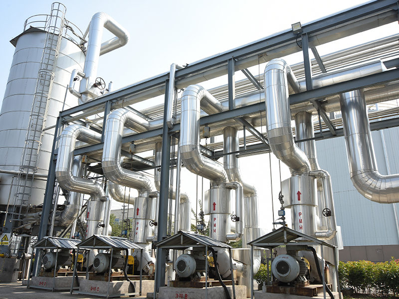
عربىA radiant tube is a closed, gas-fired or electrically heated tube installed inside an industrial furnace that transfers heat to the workpiece exclusively through thermal radiation — without any direct contact between the combustion gases and the furnace atmosphere or the material being processed. This indirect heating design is the fundamental technical solution for atmosphere-controlled furnace applications such as continuous annealing, bright hardening, carburizing, and galvanizing, where combustion products (CO₂, H₂O, NOₓ) would oxidize, decarburize, or otherwise contaminate the metal surface if allowed to enter the furnace chamber. According to the Industrial Heating Equipment Association (IHEA, 2023), radiant tubes are installed in approximately 65% of all atmosphere-controlled continuous strip and batch furnaces worldwide, representing annual sales exceeding USD 420 million in the burner and tube assembly segment alone. Understanding what a radiant tube is, how it works, which configurations exist, and how to select the right material for your operating temperature is essential knowledge for furnace engineers, metallurgical process designers, and energy management specialists.
Content
- 1 How Does a Radiant Tube Work?
- 2 What Are the Main Types of Radiant Tube Configurations?
- 3 Which Radiant Tube Configuration Should You Choose? A Direct Comparison
- 4 What Materials Are Radiant Tubes Made From?
- 5 Radiant Tube Material Selection Guide by Operating Temperature
- 6 Where Are Radiant Tubes Used? Key Industrial Applications
- 7 How to Maximize Radiant Tube Service Life and Efficiency
- 8 Frequently Asked Questions About Radiant Tubes
- 8.1 Q1: What is the difference between a radiant tube and a muffle in an industrial furnace?
- 8.2 Q2: How long does a radiant tube typically last?
- 8.3 Q3: Can radiant tubes be used with hydrogen fuel?
- 8.4 Q4: What causes a radiant tube to fail prematurely?
- 8.5 Q5: How do radiant tubes affect furnace energy efficiency?
- 8.6 Q6: What is the difference between a radiant tube and a fired heater tube in a refinery?
- 8.7 Q7: How are radiant tubes sized for a specific furnace application?
- 9 Radiant Tube Selection and Specification Checklist
How Does a Radiant Tube Work?
A radiant tube works by confining the combustion flame entirely inside the tube, heating the tube wall to temperatures of 900°C to 1,150°C (1,652°F to 2,102°F), and then radiating that heat outward as infrared energy to the furnace load — all without the combustion products ever entering the furnace atmosphere. The operating principle follows the Stefan-Boltzmann law of thermal radiation: heat flux emitted per unit area of tube surface is proportional to the fourth power of the absolute temperature difference between the tube surface and the load surface, making tube surface temperature the dominant variable in radiant heating performance.
The complete operating sequence of a gas-fired radiant tube system is as follows:
- Fuel-Air Mixing: Natural gas or propane is mixed with combustion air — either at a fixed stoichiometric ratio in conventional burners or at a lean premix ratio in low-NOₓ burners — and injected into the burner end of the tube. Combustion air is often preheated by a recuperator using exhaust gas energy, recovering 25–45% of available flue heat and raising system thermal efficiency from approximately 35–45% (cold air) to 55–70% (preheated air) per U.S. Department of Energy Industrial Heat Recovery Guidelines (DOE, 2022).
- Combustion Inside the Tube: The flame propagates along the inside of the tube from the burner end toward the return leg or exhaust end. In U-tube and W-tube configurations, the flame and hot combustion gases travel the full tube length, transferring heat progressively to the tube wall along the entire path. Flame temperature inside the tube typically reaches 1,400–1,600°C (2,552–2,912°F), significantly above the tube wall temperature, driving the radiant heat transfer outward.
- Radiant Heat Transfer to the Load: The heated tube wall emits infrared radiation proportional to its surface temperature and emissivity. Most metallic alloy radiant tubes have surface emissivity values of 0.80–0.90 in the oxidized condition — close to ideal blackbody behavior — making them highly efficient radiators. The load (steel strip, forgings, castings) absorbs this radiation and heats up uniformly across its surface facing the tube array.
- Exhaust Gas Recovery: Combustion products exit through the tube's exhaust port (separated from the furnace atmosphere by the tube wall) and pass through the recuperator to preheat incoming combustion air before being vented through the stack. In high-efficiency systems, exhaust gas temperatures leaving the recuperator can be reduced to 150–250°C (302–482°F) from initial temperatures of 900–1,050°C (1,652–1,922°F), representing heat recovery of 60–75% of available flue gas enthalpy.
What Are the Main Types of Radiant Tube Configurations?
Radiant tubes are manufactured in several geometric configurations, each offering different combustion path lengths, temperature uniformity profiles, installation footprints, and maintenance access characteristics. The configuration selection determines the tube's heat distribution pattern across the furnace and its suitability for specific furnace geometries.
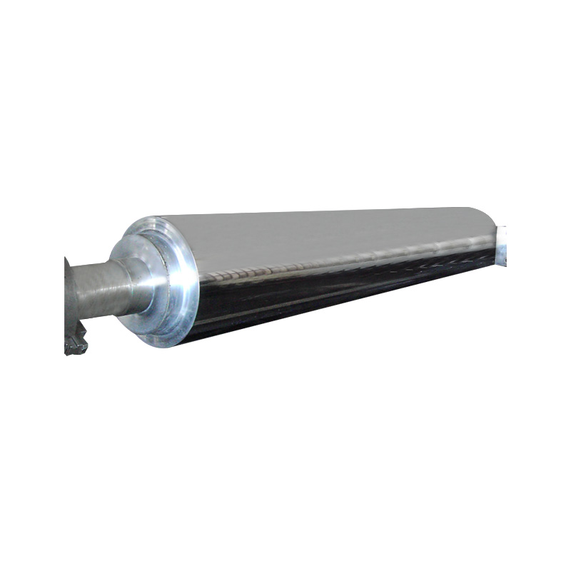
1. Straight (Single-Pass) Radiant Tube
The straight or single-pass radiant tube is the simplest configuration — a single tube open at the burner end and exhausting at the opposite end. It is primarily used in smaller furnaces, muffle furnaces, and applications where tube replacement access is available from both sides of the furnace wall. The main limitation is a pronounced temperature gradient from burner to exhaust end: the burner end runs significantly hotter than the exhaust end, creating non-uniform heat flux across the tube length. Typical temperature differential between burner end and exhaust end is 80–150°C (176–302°F) under standard operating conditions, which can result in uneven heating of wide strip or plate products if tube spacing is not carefully optimized.
2. U-Tube Radiant Tube
The U-tube radiant tube — also called a two-pass tube — features a 180-degree return bend at the far end of the furnace, with both the burner and exhaust connections at the same furnace wall. The combustion gases travel the full tube length outward, turn at the U-bend, and return along the parallel leg to the exhaust port. The return-flow hot gases preheat the incoming flow before the U-bend, improving thermal efficiency. The U-tube configuration achieves better temperature uniformity than the straight tube — typical end-to-end temperature differential is reduced to 40–80°C (104–176°F) — and allows both burner maintenance and tube replacement from a single access side. The U-tube is the most widely installed configuration in continuous annealing furnaces, galvanizing lines, and heat treatment batch furnaces worldwide.
3. W-Tube (Double-Return) Radiant Tube
The W-tube radiant tube extends the U-tube concept with a second 180-degree return, creating a four-pass combustion path within a single assembly. The longer combustion path allows more complete heat extraction from the flame and produces the best temperature uniformity of all standard configurations — end-to-end differentials as low as 20–40°C (68–104°F) are achievable. The W-tube's thermal efficiency advantage makes it particularly attractive for furnaces where the fuel cost is the dominant operating expense and where furnace width limits the achievable tube length. W-tubes are commonly specified for automotive strip steel annealing furnaces and silicon steel processing lines where process temperature uniformity of ±5°C across the strip width is a quality specification requirement.
4. P-Tube (Single-Ended Recuperative) Radiant Tube
The P-tube (also called a single-ended recuperative tube, or SER tube) is a concentric arrangement where the burner fires into a central inner tube; combustion gases travel to the closed end, reverse direction in the space between the inner tube and the outer tube wall, and return to the exhaust connection — all at the same end as the burner, in a single, hermetically closed assembly. This design eliminates all tube joints inside the furnace, dramatically reducing the risk of atmosphere contamination from tube joint leakage. The integral recuperator within the annular return path preheats combustion air to 300–600°C (572–1,112°F) using exhaust gas waste heat, achieving thermal efficiencies of 65–75% — significantly higher than external recuperator systems (Source: Combustion Engineering Associates, Radiant Tube Technology Review, 2022). P-tubes are the preferred configuration for high-temperature furnaces above 1,050°C (1,922°F) and for all applications where atmosphere integrity is the primary concern.
5. Electric Radiant Tube
Electric radiant tubes use resistance heating elements (SiC, MoSi₂, or metallic alloy elements) housed inside a protective ceramic or metallic tube. They provide the most precise temperature control of any radiant tube type — ±2°C (±3.6°F) versus ±10–20°C for gas-fired systems — and produce zero combustion byproducts, making them ideal for ultra-clean atmosphere furnaces processing semiconductor components, precision optical glass, and specialty alloys. Their principal limitation is energy cost: electric heating typically costs 2.5–4× more per unit of heat delivered than gas-fired systems in most industrial markets, limiting their use to applications where process quality justifies the premium (Source: U.S. DOE Manufacturing Energy and Carbon Footprints, 2022).
Which Radiant Tube Configuration Should You Choose? A Direct Comparison
Selecting the correct radiant tube configuration requires balancing temperature uniformity, thermal efficiency, installation footprint, maintenance access, and capital cost. The table below compares all five configurations across the criteria most relevant to industrial furnace specification:
| Configuration | Passes | Temp Uniformity | Thermal Efficiency | Max Tube Temp | Best Application |
|---|---|---|---|---|---|
| Straight (single-pass) | 1 | Poor (±80–150°C) | 35–50% | 1,050°C | Small batch furnaces, muffle ovens |
| U-Tube (two-pass) | 2 | Good (±40–80°C) | 50–65% | 1,100°C | Continuous annealing, galvanizing, general heat treatment |
| W-Tube (four-pass) | 4 | Excellent (±20–40°C) | 60–70% | 1,100°C | Automotive strip, silicon steel, tight uniformity specs |
| P-Tube / SER (single-ended recuperative) | 2 (concentric) | Very Good (±30–50°C) | 65–75% | 1,150°C | High-temp hardening, bright annealing, HPHT furnaces |
| Electric radiant tube | N/A | Outstanding (±2°C) | 95–99% (electrical to heat) | 1,300°C+ | Semiconductor, optical, specialty alloy ultra-clean processing |
Table 1: Comparison of the five main radiant tube configurations by number of passes, temperature uniformity, thermal efficiency, maximum tube temperature, and recommended industrial application. Sources: IHEA (2023), Combustion Engineering Associates (2022), DOE (2022).
What Materials Are Radiant Tubes Made From?
Material selection for a radiant tube is the single most consequential specification decision in any furnace project — it determines maximum operating temperature, creep resistance, oxidation life, carburization resistance, and total cost of ownership over the tube's service life. The four main material categories used in radiant tube manufacture are each optimized for specific temperature ranges and atmosphere conditions:
Heat-Resistant Cast Alloys (HK, HT, HP)
Cast heat-resistant alloys conforming to ASTM A297 grades HK (25Cr-20Ni), HT (15Cr-35Ni), and HP (25Cr-35Ni+Nb) are the workhorses of gas-fired radiant tube production for service temperatures up to 1,050°C (1,922°F). These alloys develop a protective chromia (Cr₂O₃) scale on their outer surface that limits further oxidation at temperature. HP alloys with niobium additions demonstrate significantly better creep rupture strength than base HP — a critical property for tubes supporting their own weight in horizontal installations at high temperature. Average service life of HP-Nb alloy radiant tubes in continuous annealing furnaces at 950°C (1,742°F) is 5 to 8 years per industry service data compiled by the ASTM A297 Alloy Review Committee (2021).
Wrought Nickel-Chromium Alloys (Alloy 601, 602CA)
Wrought alloys such as Alloy 601 (60Ni-23Cr-1.4Al) and Alloy 602CA (62Ni-25Cr-2.3Al) are used for radiant tubes requiring service temperatures of 1,050–1,150°C (1,922–2,102°F) with superior cyclic oxidation resistance. The aluminum addition in these alloys promotes the formation of a slow-growing Al₂O₃ alumina scale rather than a chromia scale at the highest temperatures, providing oxidation protection 3–5 times longer than chromia-forming alloys under cyclic heating conditions (Source: High Temperature Alloys for Industrial Furnaces, Special Metals Corporation Technical Report, 2020). These alloys are specified for rapid-cycle furnaces used in automotive parts heat treating, where frequent temperature cycling from 20°C to 1,100°C (68°F to 2,012°F) is the primary degradation mechanism.
Silicon Carbide (SiC) Ceramic Radiant Tubes
Silicon carbide radiant tubes are the standard solution for furnace applications requiring continuous service temperatures above 1,150°C (2,102°F) up to a maximum of approximately 1,400°C (2,552°F). SiC ceramic has thermal conductivity approximately 3–4 times higher than metallic heat-resistant alloys, enabling more efficient heat transfer from the combustion gases to the tube outer wall surface per unit of temperature difference. The primary limitations of SiC tubes are brittleness (requiring careful handling and thermal shock avoidance during startup) and limited ability to accommodate bending loads — SiC tubes cannot be used in U or W configurations without ceramic joints that introduce leakage risk, so they are typically supplied as straight tubes only. Per ASTM C1161 flexural strength data, recrystallized SiC radiant tube specimens have a mean flexural strength of 170–220 MPa at room temperature, dropping to 150–190 MPa at 1,200°C — adequate for self-weight loading but requiring careful support design in long horizontal installations.
Oxide-Dispersion Strengthened (ODS) Alloys
ODS alloys — iron-chromium-aluminum alloys with yttria (Y₂O₃) dispersoids mechanically alloyed into the matrix — represent the frontier of metallic radiant tube material technology, offering service temperatures of 1,200–1,300°C (2,192–2,372°F) in combination with excellent thermal fatigue resistance. ODS tubes have been successfully installed in direct-fired ceramic tunnel kilns and special atmosphere glass-melting furnaces where conventional nickel alloys fail by creep within months at operating temperature. Their high current cost (approximately 4–6× the price per kg of HP-Nb alloy) limits adoption to niche high-value applications, but as manufacturing scale increases, wider industrial adoption is projected per International Journal of Refractory Metals and Hard Materials (2022).
Radiant Tube Material Selection Guide by Operating Temperature
The correct radiant tube material must be specified from the operating temperature upward — not downward from cost. Under-specifying tube material for operating temperature is the most common root cause of premature tube failure in industrial furnaces. The table below provides a definitive selection guide:
| Material | Max Continuous Temp | Cyclic Temp Resistance | Typical Service Life | Relative Cost | Best Application |
|---|---|---|---|---|---|
| HK / HT cast alloy | 1,000°C (1,832°F) | Moderate | 3–5 years | Low (1×) | General heat treatment, carburizing below 950°C |
| HP-Nb cast alloy | 1,050°C (1,922°F) | Good | 5–8 years | Medium (1.5×) | Continuous annealing, galvanizing, batch hardening |
| Alloy 601 / 602CA wrought | 1,150°C (2,102°F) | Excellent | 6–10 years | High (2.5–3×) | Rapid-cycle hardening, bright annealing, high-temp HPHT |
| Silicon carbide (SiC) ceramic | 1,400°C (2,552°F) | Limited (thermal shock risk) | 3–7 years (no thermal shock) | Medium-high (2×) | Ceramic kilns, glass melting, non-ferrous smelting |
| ODS FeCrAl alloy | 1,300°C (2,372°F) | Outstanding | 8–15 years (projected) | Very high (4–6×) | Specialty glass, advanced ceramics, hydrogen atmospheres |
Table 2: Radiant tube material selection guide by maximum continuous operating temperature, cyclic resistance, typical service life, relative cost, and best industrial application. Sources: ASTM A297 (2021), Special Metals Corporation (2020), International Journal of Refractory Metals (2022).
Where Are Radiant Tubes Used? Key Industrial Applications
Radiant tubes are used wherever indirect gas-fired heating is required to maintain a controlled protective or reactive atmosphere inside the furnace while still achieving efficient thermal input. The following industries and processes represent the primary application sectors:
- Continuous Strip Steel Annealing: The largest single application of radiant tubes globally. Continuous annealing lines process cold-rolled steel strip at speeds of 100–600 meters per minute through furnaces 60–150 meters long, maintaining a hydrogen-nitrogen protective atmosphere that prevents oxidation and achieves bright annealed surface finish. A single continuous annealing line typically uses 200–600 radiant tube assemblies arranged in banks along the furnace walls and roof (Source: AIST Iron and Steel Technology, 2022).
- Hot-Dip Galvanizing Lines: Galvanizing furnace sections (the annealing and reduction sections before the zinc bath) use radiant tubes to heat steel strip in a hydrogen-nitrogen atmosphere to 750–850°C (1,382–1,562°F) to reduce surface iron oxides before zinc immersion — a prerequisite for adequate zinc adhesion and coating quality. Poor radiant tube maintenance is the leading non-quality-related cause of strip surface defects on galvanizing lines, per ILZRO Galvanizing Line Quality Review (2021).
- Gas Carburizing and Carbonitriding: Case-hardening furnaces use radiant tubes to heat steel parts in a carbon-rich endothermic atmosphere (typically 40% CO, 40% H₂, 20% N₂) to 900–960°C (1,652–1,760°F) to diffuse carbon into the surface layer. The sealed tube design prevents the enriched atmosphere from contacting the burner flame, which would ignite and destroy the carefully maintained carbon potential.
- Bright Hardening of Tool Steels and Stainless Steel: Components requiring a bright, oxide-free surface after hardening are processed in atmosphere furnaces heated by radiant tubes under pure hydrogen or nitrogen atmospheres. Bright hardening eliminates the scale removal operations (shot blasting, pickling) required after conventional open-flame hardening, reducing total processing cost by 15–25% per part.
- Sintering of Powder Metal Components: Powder metal parts (gears, bearings, structural components) are sintered in continuous mesh-belt or pusher furnaces at 1,100–1,300°C (2,012–2,372°F) under dissociated ammonia (25% N₂ / 75% H₂) atmospheres. Radiant tubes provide the indirect heating that maintains both the high temperature and the reducing atmosphere simultaneously — essential for achieving full densification without surface oxidation of the sintered part.
- Non-Ferrous Metal Processing: Aluminum homogenization furnaces, copper wire annealing lines, and nickel strip processing all use radiant tubes in protective atmospheres to achieve controlled heat treatment without surface contamination that would affect electrical conductivity, corrosion resistance, or formability.
How to Maximize Radiant Tube Service Life and Efficiency
Premature radiant tube failure is one of the most costly unplanned maintenance events in a continuous processing furnace, requiring furnace shutdown, atmosphere purge, tube replacement, and atmosphere re-establishment — a sequence that can cost $50,000–$300,000 per event in lost production and maintenance labor on a high-volume strip annealing line. Seven practices consistently extend tube service life and maintain system efficiency:
- Control Combustion Air-to-Fuel Ratio Precisely: Operating at excess air greater than 10% above stoichiometric causes oxidizing conditions inside the tube that accelerate internal scaling and hot corrosion of the tube bore. Operating below stoichiometric (fuel-rich) creates reducing conditions that promote carburization of metallic tubes — a different but equally damaging attack mode. Install O₂ trim control systems that maintain combustion at 2–5% excess air continuously.
- Avoid Thermal Shock During Startup and Shutdown: Ramp furnace temperature at a maximum of 100°C per hour (180°F/hr) during startup from cold condition. Thermal shock from rapid heat-up cracks ceramic tubes, distorts metallic tubes beyond their yield stress at temperature, and accelerates fatigue crack initiation at weld joints on return bends. Most radiant tube manufacturer warranties are voided by documented thermal shock events.
- Monitor Tube Wall Temperature with Infrared Thermometry: Regular thermal imaging of tube arrays during operation identifies hot spots (indicating internal coking, flame impingement, or uneven combustion) before they progress to tube failure. Any tube section running more than 50°C above its neighbors in the same zone should be investigated immediately for burner malfunction.
- Inspect for Atmosphere Leaks at Tube Seals Quarterly: Even a pinhole leak at a tube-to-wall seal allows furnace atmosphere (hydrogen in annealing furnaces) to enter the tube or combustion gas to enter the furnace — both scenarios are immediately dangerous and degrade product quality. Use portable H₂ or O₂ detectors at each tube penetration quarterly, and replace ceramic fiber seals at the first sign of degradation.
- Rotate Tube Position at Each Replacement: In multi-tube furnace arrays, tube thermal exposure varies significantly by position (center versus edge of the furnace, floor versus roof). Rotating tubes between positions at scheduled replacements equalizes accumulated creep damage and extends the productive life of the entire tube inventory by 15–25%.
- Clean Internal Coking Deposits Annually: Natural gas combustion at fuel-rich conditions deposits carbon (coke) inside the tube bore, which acts as an insulator reducing heat transfer efficiency. Annual inspection and chemical cleaning (hot air burnout at controlled conditions) of tubes that show coking restores heat transfer efficiency and reduces tube wall temperature for the same heat output.
- Track Creep Elongation on Horizontal Tubes: Metallic radiant tubes installed horizontally elongate under their own weight over time at high temperature — a process called creep sagging. Measure tube centerline deflection annually; deflections exceeding 10 mm per meter of tube length indicate the tube is approaching its usable creep life limit and should be scheduled for replacement at the next planned outage.
Frequently Asked Questions About Radiant Tubes
Q1: What is the difference between a radiant tube and a muffle in an industrial furnace?
A radiant tube is an individual, gas-fired or electrically heated tube that heats the furnace atmosphere indirectly through its outer surface. A muffle is a larger, typically box-shaped or arch-shaped refractory enclosure that separates the combustion chamber from the work chamber across a full section of the furnace — heat passes through the muffle wall by conduction and radiation. Radiant tubes offer higher heating rates, more precise zone-by-zone temperature control, and easier individual replacement than muffles. Muffles provide a more uniform heating environment over large workpiece cross-sections but have significantly higher thermal mass that slows both heat-up and cool-down rates — making them less suitable for rapid thermal cycling applications.
Q2: How long does a radiant tube typically last?
Service life of a radiant tube varies significantly with material, operating temperature, and thermal cycling frequency. As a general guideline per IHEA industry data: HK/HT cast alloy tubes at 950°C average 3–5 years; HP-Nb cast alloy tubes at 1,000–1,050°C average 5–8 years; Alloy 601/602CA wrought tubes at 1,100–1,150°C average 6–10 years; SiC ceramic tubes in carefully controlled thermal environments average 3–7 years. The most common failure modes are creep distortion (sagging, ovalization), oxidation-induced wall thinning, and thermal fatigue cracking at weld joints — all of which develop progressively over time and can be tracked through scheduled inspection to enable planned rather than emergency replacement.
Q3: Can radiant tubes be used with hydrogen fuel?
Yes — radiant tubes can be fired with hydrogen fuel, and this is increasingly specified for low-carbon steel processing applications. Hydrogen combustion produces only water vapor as a byproduct (no CO₂), and the higher flame temperature of hydrogen (approximately 2,100°C adiabatic versus 1,950°C for natural gas) increases radiant output per tube. However, hydrogen flame characteristics (shorter, less luminous flame, higher risk of flashback) require burner modification from natural-gas designs. Material compatibility must also be verified: hydrogen atmospheres at high temperature cause hydrogen embrittlement in certain steel alloys, though the high-chromium, high-nickel alloys used in radiant tubes are generally hydrogen-compatible. Per International Energy Agency, Hydrogen in Industry (2023), hydrogen-fired radiant tube furnaces are now operational at pilot scale in several European steel annealing facilities.
Q4: What causes a radiant tube to fail prematurely?
The three most common causes of premature radiant tube failure, in order of frequency, are: first, thermal shock from excessively rapid heat-up or cool-down cycles that exceed the tube material's thermal fatigue resistance; second, flame impingement — the flame contacting the tube bore wall directly rather than burning as a free flame, creating local hot spots 200–300°C above the average tube wall temperature that cause localized creep and oxidation failure; and third, incorrect combustion ratio (excessive excess air or fuel-rich operation) that creates either aggressive oxidizing or carburizing internal attack on the tube bore surface. All three causes are preventable through proper burner commissioning, operating procedure control, and regular maintenance inspection.
Q5: How do radiant tubes affect furnace energy efficiency?
Radiant tube system thermal efficiency is determined primarily by the exhaust gas temperature leaving the recuperator relative to the tube firing temperature. Without heat recovery (no recuperator), a radiant tube system operating at 1,000°C tube temperature with 850°C exhaust gas achieves approximately 35–40% thermal efficiency — meaning 60–65% of the fuel energy is lost as waste heat in the exhaust. Adding an integral recuperator (as in P-tube / SER design) that preheats combustion air to 500°C raises efficiency to 65–75%, reducing fuel consumption by approximately 45–55% for the same heat output. The DOE's Industrial Technologies Program (2022) estimates that widespread adoption of recuperative radiant tube systems across U.S. industrial heat treatment could reduce sector natural gas consumption by approximately 35 trillion BTU per year.
Q6: What is the difference between a radiant tube and a fired heater tube in a refinery?
Radiant tubes in industrial furnaces and fired heater tubes in refinery process heaters share the same fundamental principle — the tube wall radiates heat from an external heat source — but differ in application and design. Industrial radiant tubes heat a furnace atmosphere (and by extension, the workpieces in it) from the outside of the tube, with the combustion gases inside the tube and the process atmosphere outside. Refinery fired heater tubes carry the hydrocarbon process stream inside the tube, which is heated by burner radiation from outside the tube — the reverse arrangement. The materials, operating pressures, and regulatory frameworks governing the two applications are entirely separate (ASME B31.3 piping code for fired heater tubes versus ASTM A297 for industrial radiant tubes).
Q7: How are radiant tubes sized for a specific furnace application?
Radiant tube sizing for a furnace involves calculating the required installed heat transfer area (m²) to meet the furnace's peak heat demand (kW) at the target tube surface temperature, then dividing by the available furnace wall area per tube to determine the number of tubes required. The governing equation is Q = ε × σ × A × (T_tube⁴ − T_load⁴), where Q is heat flux (W), ε is tube emissivity (typically 0.85), σ is the Stefan-Boltzmann constant (5.67 × 10⁻⁸ W/m²·K⁴), A is tube surface area (m²), and T_tube and T_load are tube and load absolute temperatures (K). In practice, this calculation is performed with commercial furnace modeling software (CFD or zone method analysis) that accounts for view factors between multiple tubes and the load geometry, furnace wall reflectivity, and load thermal mass. Tube diameter selection (typically 100–200 mm for standard applications) balances per-tube heat output, structural self-weight, and replacement cost.
Radiant Tube Selection and Specification Checklist
- Define maximum tube wall temperature (not furnace atmosphere temperature) — tube wall runs 50–150°C above the furnace set point depending on configuration and firing rate.
- Select tube material from operating temperature upward: HK/HT below 1,000°C; HP-Nb to 1,050°C; Alloy 601/602CA to 1,150°C; SiC ceramic to 1,400°C.
- Choose configuration based on uniformity requirements: straight for simple batch applications; U-tube for standard continuous lines; W-tube for tight ±5°C strip uniformity; P-tube for highest efficiency and atmosphere integrity.
- Specify a recuperative burner or integral recuperator for any new installation — non-recuperated radiant tube systems operating above 900°C waste 60–65% of fuel input as exhaust heat.
- Install O₂ trim combustion control on each firing zone to maintain 2–5% excess air and prevent internal tube oxidation or carburization.
- Plan for thermal shock prevention: specify maximum heat-up and cool-down rates of 100°C/hr for metallic tubes and 50°C/hr for SiC ceramic tubes in operating procedures.
- Schedule annual infrared thermography surveys of all tube arrays during operation to identify developing hot spots, flame impingement, and uneven combustion before they cause tube failure.