English
 русский
 Español
 عربى
عربىQuick Answer: Choosing the right heat treatment tray depends on four key factors: the process temperature, the atmosphere type (oxidizing, reducing, or vacuum), the load weight and geometry, and the tray material's thermal and mechanical properties. Match the alloy composition of the tray to the specific demands of annealing, quenching, carburizing, nitriding, or sintering to maximize service life and part quality.
Content
- 1 What Is a Heat Treatment Tray and Why Does It Matter?
- 2 Step 1 – Understand the Key Parameters of Your Process
- 3 Step 2 – Compare Heat Treatment Tray Materials
- 4 Step 3 – Match the Tray to Specific Heat Treatment Processes
- 5 Step 4 – Evaluate Tray Design and Geometry
- 6 Process-to-Tray Selection Summary Table
- 7 Tips to Extend Heat Treatment Tray Service Life
- 8 Frequently Asked Questions (FAQ)
- 9 Conclusion
What Is a Heat Treatment Tray and Why Does It Matter?
A heat treatment tray — also referred to as a furnace tray, heat-resistant basket, or fixture — is a load-bearing component used inside industrial furnaces to support parts during thermal processing. It must endure extreme temperatures, thermal cycling, corrosive atmospheres, and mechanical stress, all while maintaining dimensional stability so that the workpieces processed on it meet tight tolerances.
Selecting the wrong heat treatment tray leads to premature failure, contamination of treated parts, furnace downtime, and increased operating costs. The right choice, by contrast, extends service intervals and ensures repeatable metallurgical results.
Step 1 – Understand the Key Parameters of Your Process
Before evaluating any tray, you must define your process parameters clearly:
- Maximum operating temperature (°C / °F) — determines alloy grade requirement
- Atmosphere type — air, endothermic gas, nitrogen, hydrogen, vacuum, or salt bath
- Thermal cycling frequency — continuous vs. batch operations impose different fatigue demands
- Load weight per tray — determines required creep resistance and cross-section design
- Part geometry and contact requirements — affects tray surface design (flat, perforated, grid, basket)
- Quench method — oil, gas, or water quench induces thermal shock; tray must resist cracking
Step 2 – Compare Heat Treatment Tray Materials
Material selection is the single most critical decision. Below is a comparative overview of the most widely used alloy families for heat treatment trays:
| Alloy / Material | Max Temp (°C) | Key Strength | Limitation | Best For |
| HH (25Cr-12Ni) | 980°C | Cost-effective, good oxidation resistance | Limited above 980°C; lower creep strength | Annealing, normalizing, tempering |
| HK (25Cr-20Ni) | 1100°C | Higher creep resistance, excellent oxidation resistance | Moderate cost; poor in carburizing atmosphere | Solution annealing, bright annealing |
| HP (35Cr-25Ni + Nb) | 1150°C | Excellent high-temp strength, good carburization resistance | Higher cost; brittle after long exposure | Carburizing, petrochemical furnaces |
| HT (15Cr-35Ni) | 1090°C | High nickel content → excellent thermal cycling resistance | Lower chromium = weaker oxidation protection | Quench-and-temper lines, frequent cycling |
| Ni-Cr-W Superalloys | 1200°C+ | Superior creep strength, oxidation & carburization resistance | High cost; heavy weight | Sintering, aerospace component heat treatment |
| Silicon Carbide (SiC) | 1650°C | Extreme temperature capability, low thermal mass | Brittle; poor thermal shock resistance; expensive | Ceramic sintering, very high-temp processes |
Step 3 – Match the Tray to Specific Heat Treatment Processes
Annealing
Annealing typically operates between 700°C and 1050°C in air or controlled atmosphere. A heat treatment tray made from HH or HK alloy is usually sufficient. The priority is oxidation resistance and dimensional stability under moderate loads. Perforated or grid-style trays improve atmosphere circulation around parts.
Quench Hardening
Quenching subjects the tray to severe thermal shock — the part goes from 850–950°C into oil, polymer, or gas quench in seconds. The tray must withstand repeated rapid cooling cycles without cracking. High-nickel alloys (HT grade) with better ductility and thermal fatigue resistance are recommended. Basket designs are preferred over solid-bottomed trays to allow rapid quench media penetration.
Carburizing & Carbonitriding
Carburizing atmospheres (endothermic gas with methane or propane additions) aggressively attack iron-based materials. High chromium content in the heat treatment tray forms a protective Cr₂O₃ layer. HP alloy or modified HP+Nb grades are the industry standard here. Avoid HH grade; its lower chromium content cannot prevent carbon ingress at 920–980°C over repeated cycles.
Nitriding & Nitrocarburizing
Nitriding occurs at lower temperatures (500–570°C) in ammonia-rich atmospheres. The chemical challenge is nitrogen embrittlement of the tray surface. Austenitic stainless steel (316L or 310S) trays are widely used for nitriding because the stable austenite phase resists nitrogen absorption better than ferritic alloys. Thin-walled, lightweight designs help minimize nitrogen activity on the tray itself.
Vacuum Heat Treatment
In vacuum furnaces, there is no oxidizing atmosphere to form protective oxide scales on the tray. Material selection shifts toward molybdenum alloys, graphite, or nickel-based superalloys, depending on temperature. Carbon contamination from graphite trays must be considered when processing reactive materials such as titanium alloys.
Sintering
Sintering processes span from 1100°C to over 1400°C. At the high end, only ceramic trays (alumina, silicon carbide, or zirconia) or advanced superalloy trays are viable. The tray must not react with the sintered powder. Alumina trays are the most common choice for powder metallurgy sintering due to their chemical inertness.
Step 4 – Evaluate Tray Design and Geometry
Beyond material, the physical design of the heat treatment tray significantly impacts performance:
- Solid-bottom trays — best for small batch work with uniform flat parts; limits atmosphere flow
- Perforated trays — allow gas and quench media to reach parts quickly; good for carburizing and quenching
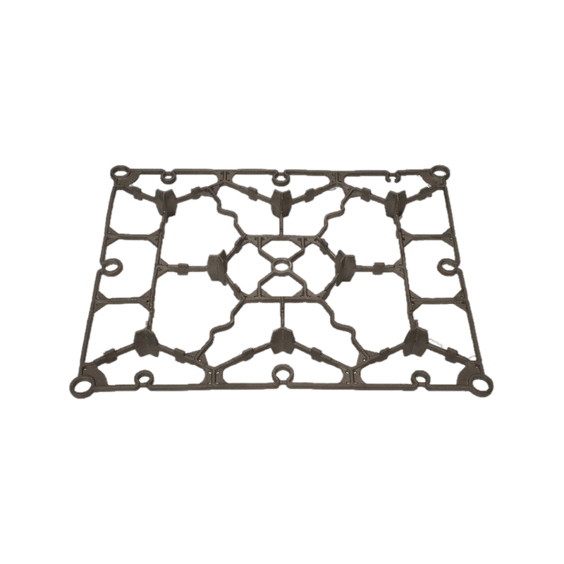
- Grid/bar trays — maximize airflow and minimize contact with the tray; ideal for thin or delicate parts
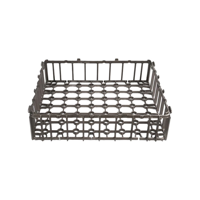
- Basket trays — enclosed on all sides; suitable for small parts like fasteners, bearings, and gears
- Stackable trays — increase furnace throughput; must have a high creep resistance to bear stacked weight at temperature
Wall thickness and rib reinforcement must be engineered so that the tray does not sag under load at operating temperature. A tray that distorts unevenly causes parts to shift position and may result in non-uniform heat distribution and hardness gradients.
Process-to-Tray Selection Summary Table
| Process | Temperature Range | Atmosphere | Recommended Tray Material | Preferred Design |
| Annealing | 700–1050°C | Air / N₂ | HH, HK | Solid / Perforated |
| Quench Hardening | 800–980°C | Endothermic / N₂ | HT, HK | Basket / Perforated |
| Carburizing | 900–980°C | Endothermic + Enriched | HP, HP+Nb | Basket / Grid |
| Nitriding | 500–570°C | NH₃ / Dissociated NH₃ | 316L SS, 310S | Perforated / Grid |
| Vacuum HT | 900–1300°C | Vacuum / Partial pressure | Mo alloy, Ni superalloy, Graphite | Grid / Bar |
| Sintering | 1100–1450°C | H₂ / N₂-H₂ / Vacuum | Alumina, SiC, Ni superalloy | Flat / Solid ceramic |
Tips to Extend Heat Treatment Tray Service Life
- Rotate trays regularly — equal exposure to the hottest furnace zones distributes wear evenly across the tray fleet
- Avoid overloading — loading beyond rated capacity accelerates creep distortion; always follow the manufacturer's maximum load specification
- Pre-oxidize new trays — slowly ramping new metal trays to operating temperature in air before first use builds a protective oxide layer
- Inspect for cracks regularly — hairline cracks from thermal fatigue grow rapidly under continued cycling; retire cracked trays before they fail in-furnace
- Clean off carbon deposits — build-up of carbon on trays used in carburizing changes thermal mass and can contaminate parts
- Store properly — store trays flat or on edge (not stacked unevenly) to prevent room-temperature distortion
Frequently Asked Questions (FAQ)
Conclusion
Selecting the correct heat treatment tray is not a one-size-fits-all decision. It requires a systematic evaluation of process temperature, atmospheric chemistry, thermal cycling severity, load requirements, and tray geometry. By matching the right alloy — whether HH, HK, HP, high-nickel superalloy, or ceramic — to your specific heat treatment process, you can significantly reduce tray replacement frequency, improve part quality consistency, and lower total operating cost.